

ChiefJeet
-
Posts
71 -
Joined
-
Last visited
Content Type
Profiles
Forums
Gallery
Posts posted by ChiefJeet
-
-
The composition of the shed roof is joists overlaid by 18mm ply +125mm of insulation then another layer of ply and finished with felt. Is there a way of showing these construction material I the section elevation. I can do a workaround by increasing the rafter size and then draw cad lines and fills to show the construction. Is there a better way of detailing this, similar to wall construction?

-
Wall Piers
in Q&A
I wish to create wall piers as shown in the image. The pier size is 325x100 projecting out from the wall.
The external wall thickness is 275mm and I try to break the wall so I can increase the thickness of it but it does not work. Please help. Attached the video showing my attempts and the plan file

-
Snap settings
in Q&A
I have my grid snap settings at 25mm but when I draw, the objects are often 12 or 13mm out which is half of 25mm. I can manually resize them but don't know what is causing it in the first place.
I have attached a plan file and video recording for identifying the problem.
I also have a wall sticking out from the loft plan and a shed roof corner sloping when it should not.
Please help

-
Thanks Eric but I have not drawn any framing and infact, I have not got to that stage yet. In my plan file- display options, every thing staring with framing is unchecked (hidden) but the framing still shows in the layout. In addition, a lot of the other details on elevations are not visible. Kindly have a look at the attached plan and the layout sheet above.
-
I have sent floor plan and elevations to layout sheet but is showing framing in floor plan and in elevations as shown it the attached clips. I have tried showing and hiding roof planes but it does not makes any difference. Please help. Plan file and layout files attached.

-
 1
1
-
-
Still pondering over this issue. Any help guys? The plan file is attached above.
-
1
-
-
Thanks David. I did attach a plan file.see above.
I do have "boxed eaves" checked and that only draws about 225mm box and then the underside slopes along the rafter.
With regards to the floor gap, I would like to find the cause. Playback see the attached file above.
-
I have drawn a bow window on ground floor and on the first floor. The floor section is transparent through the bay window wall and I cannot get rid of it. Please help with this issue.
Also I would like to extend the soffit all the way to the wall and I cannot figure out how this can be done. Please help as I have spent sever hours trying to figure it out.

-
Still having issue with overlapping walls. Eric referred me to a link but it has not resolved the problem. Further help would be appreciated.
-
1
-
-
I'm afraid, it does not help. Cannot locate "framing reference to remove" in cavity wall or the solid wall. Tried with "through wall at end and start" ticked and it only makes the overlap longer. File added for demo.
-
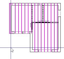
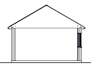
I keep getting a situation where the cavity wall overlaps the existing wall as shown on the left side of the image. The overlap will then also be displayed on the side elevation. Strangely, it only happens on one side. I have searched on the forum for overlapping walls but could not find anything. A help on this would be appreciated.

-
I have taken a normal Cross Section which shows roof framing but also the other items in the background. To avoid seeing items in the background, I took a backclipped section but this do not show any roof framing. Is there a work around this?

-
1
-
-
Text, Notes
in Q&A
I have contacted Chief and they said what Eric said. It's left there by mistake
-
No. Back clipping section
-
I think I got it. Side clipping section?
-
Thank you Eric.
The section in the clip is taken through the window but in the background, there is a solid fill, perhaps the door in the background. How can I clean the section so only entities the section is cutting across are visible and then I would be able to hatch the walls?.
-
I have searched for this topic and have come across suggestions about using Cad to enhance the section. Can the fill patterns same as on the floor plan be applied to sections?

-
Thanks Eric but I tried all that and it does not give me editing handle. Pls see the vide
-
Text, Notes
in Q&A
Thanks in advance
-
Text, Notes
in Q&A
I would like to ask the same question as Brewer. I understand that there are no custom layers but this layer (Text, Notes) is present in HD Pro. So what objects are programmed to go into this layer. I have tried Rich text, Call outs and all the entities listed under Cad but none goes into that layer. What is the properties of Notes?
-
In the Layout sheet, I cannot seems to move the label so the gap between the view border and the label is not so much. David di a video on this few years back where he could move it around with X premier. On my PC it does not allow me to move. Every time I select the label, it selects the whole view. Please help. Layout file attached.

-
I have drawn a circular wall as shown in the clip below but it is invisible in the elevation. I have check the properties of the wall and it is not invisible. I have placed one window in the wall and it can be seen standing in iscolation. I have drawn gable roof over it and don't know if the roof is causing this issue. Please help. File attached.

-
Thank you Eric. You either have very sharp eyes to notice the 13mm off alignment or you new what the problem was. The mis-alignment was not intentional but I could not get rid off it. It probably occurred by snapping onto another object or to intersection. You solved two problems in one. Thank you
-
I have Auto build roof checked and the default pitch set to 35 degree but the roof keeps producing two different pitches. When I select left and the right wall, the properties of both walls states the pitch to be 35 deg but left roof plane keeps drawing at 22.5 deg. If I select the right side of roof plane in elevation view ,its "Top of wall plate" is locked and if I select the left hand roof plane its Baseline height is locked but cannot change it to "Top of wall plate" to be locked because it says NA.. I keep deleting it but it keeps rebuilding in the same location. Drawing file attached. Please someone help to resolve this issue.


Shed roof structure
in Q&A
Posted
Thanks David